


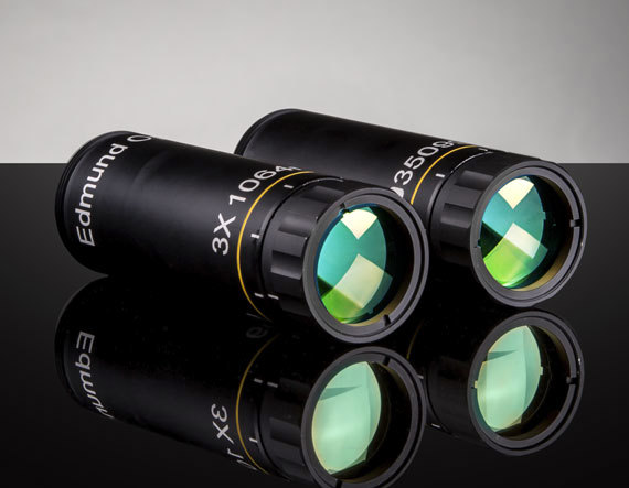
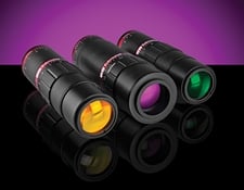
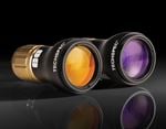
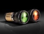
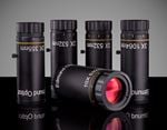
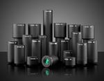
雷射擴束鏡
雷射資源指南第6.1, 6.2, 6.3, 6.4 及 6.5部份
雷射 擴束鏡 可增加平行輸入光束的直徑,使其成為更大的平行輸出光束,用於雷射掃描、干涉計量及遠端感測等應用。現代光束擴束器為無焦系統,物體光束進出時,均與內部光學元件光學軸保持平行。這代表整個系統都沒有焦距。
Telescope Theory
Optical telescopes, traditionally used to view distant objects such as celestial bodies in outer space, are divided into two types: refracting and reflecting. Refracting telescopes utilize lenses to refract, or bend, light, while reflecting telescopes utilize mirrors to reflect light.
There are two categories of refracting telescopes: Keplerian and Galilean. A Keplerian telescope consists of lenses with positive focal lengths separated by the sum of their focal lengths (圖 1). The lens closest to the object being viewed, or source image, is called the objective lens, while the lens closest to the eye, or image created, is called the image lens.
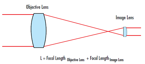
圖 1: Keplerian telescope
A Galilean telescope consists of a positive lens and a negative lens that are also separated by the sum of their focal lengths (圖 2). However, since one of the lenses is negative, the separation distance between the two lenses is much shorter than in the Keplerian design. While using the effective focal length of the two lenses will provide a good approximation of the total length, using the back focal length will provide the most accurate length.
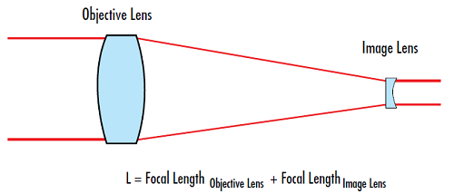
圖 2: Galilean telescope
擴束鏡的放大倍率 (MP) 或反向放大,是以物鏡及成像透鏡的焦距決定。
If the magnifying power is greater than 1, the telescope magnifies. When the magnifying power is less than 1, the telescope minifies.
擴束鏡理論
In a laser beam expander, the placement of the objective and image lenses is reversed. 克卜勒式擴束鏡由兩個正焦距透鏡組成,以其焦距總和進行分隔。這類擴束鏡提供高擴束率,可進行空間濾光,因為其中可讓平行輸入光束聚焦在物鏡與影像透鏡之間的一光點,在系統內部產生雷射能量集中的一點 (圖 3)。不過這會加熱透鏡之間的空氣,讓光線偏移光學路徑,並可能造成波前誤差,特別是在高功率雷射應用中。
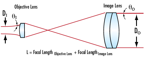
圖 3:克卜勒式擴束鏡具有內對焦,不利於高功率應用,但適用於較低功率應用的空間濾光

圖 4: 伽利略式擴束鏡沒有內對焦,是高功率雷射應用的理想選擇
When using the Keplerian or Galilean designs in laser beam expander applications, it is important to be able to calculate the output beam divergence. This determines the deviation from a perfectly collimated source. The beam divergence is dependent on the diameters of the input and output laser beams.
放大倍率 (MP) 現在可利用光束發散性或光束直徑表示。
公式 4 and 公式 5,顯示輸出光束直徑 (D0) 增加時,輸出光束發散性 (θO) 就會減少,反之亦然。因此在使用光束擴束器盡可能縮小光束時,其直徑將縮小,但雷射發散性將增加。獲得小型光束的代價,就是產生大發散角。
In addition, it is important to be able to calculate the output beam diameter at a specific working distance (L). The output beam diameter is a function of the input beam diameter and the beam divergence after a specific working distance (L) (圖 5).

圖 5: 雷射輸入光束直徑及發散性,可用於計算特定工作距離的輸出光束直徑
Laser beam divergence is specified in terms of a half angle, which is why a factor of 2 is required in the second term in 公式 6.
A beam expander will increase the input beam and decrease the input divergence by the Magnifying Power. Substituting 公式 4 and 5 with 公式 6 results in the following:
應用 1: 降低能量密度
擴束鏡會讓光束區域隨其放大倍率以平方增加,不會大幅影響光束內部的總能量。這樣可以減少光束功率密度及輻照度,延長雷射元件的使用壽命,降低雷射誘發損傷機率,並可使用更經濟實惠的鍍膜及光學元件。
應用 2: 盡可能縮小遠處光束直徑
雖然聽起來不是很能直覺理解,但使用光束擴束鏡增加雷射直徑,可能造成雷射孔徑遠處的光束直徑變小。光束擴束鏡會依據特定擴大倍率增加輸入雷射光束,同時也會以相同的擴大倍率減少發散性,造成遠處更小的平行光束。
Example
A numerical example to explore the previously mentioned beam expander equations:
Initial Parameters
Beam expander magnifying power = MP = 10X
Input beam diameter = 1mm
Input beam divergence = 0.5mrad
Working distance = L = 100m
Calculated Parameter
Beam diameter at distance L:
Compare this to the beam diameter without using a beam expander by using 公式 6.
Using a 10X beam expander reduced the output beam diameter 100m away by over a factor of 5 when compared to the same laser without a beam expander.
應用 3: 盡可能縮小聚焦光點大小
光點大小一般定義為:從最大輻照度中心點,至強度下降為初始值 1/e2 點之間的徑向距離 (圖 6)。理想透鏡的聚焦光點大小,可利用波長 (λ)、透鏡焦距 (f )、輸入光束直徑 (DI)、透鏡折射指數 (n) 及光束 M2 係數計算求得,代表與理想高斯光束之間的變化程度。
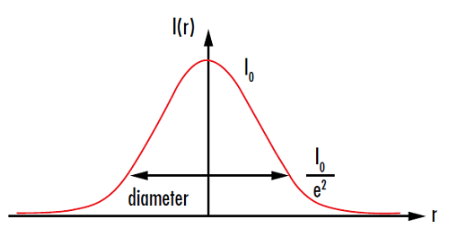
圖 6: 量測光點大小的位置,通常是在強度 I (r ) 降低至初始值 I0 的 I/e2處
繞射及像差組合是決定光點大小的基本因素,在 圖 7中分別以紅色及藍色表示。一般來說,聚焦雷射光束時,會假設球面像差是唯一及主要的像差類型,因此 公式 11 僅將球面像差列入考量。就繞射而言,焦距越短,光點就越小。更重要的是,輸入光束直徑越大,光點就越小。
擴大系統內部的光束,就可以將輸入直徑 (D) 增加 MP 倍,並將發散性減少 MP 倍。光束向下聚焦至小光點時,就理想的繞射極限光點而言,該光點會比未擴大光束小 MP 倍。不過這種方式的代價就是球面像差,因為球面像差會隨輸入光束直徑而增加。
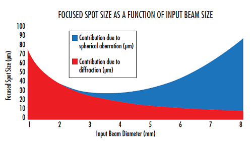
圖 7: 在小的輸入光束直徑,聚焦光點大小為繞射極限。隨著輸入光束直徑增加,球面像差就會開始主宰光點大小
應用 4:補償輸入雷射光束變異性
大部分商用雷射會在孔徑指定雷射的輸出光束直徑,公差通常是 10%以上。對許多雷射應用而言,系統最後需要指定光束直徑。其中可在系統中加入可變光束擴束鏡,用於補償個別雷射裝置之間的變異性,確保最終光束直徑對所有系統保持一致。
Beam Expander Selection Criteria
When choosing a beam expander for an application, certain criteria must be determined in order to achieve the correct performance.
Sliding vs. Rotating Divergence Adjustment:
The mechanics used to focus a beam expander or change the magnification of a variable beam expander are typically classified into two different types: sliding and rotating. Rotating divergence adjustment, such as threaded focusing tubes, rotate the optical elements during translation. They have a lower cost than sliding divergence adjustment due to their simplified mechanics, but they create the potential for beam wander due to the element rotation (圖 8).
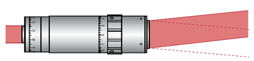
圖 8: Exaggerated illustration of the beam wander that may be caused by rotating focus mechanisms
Sliding divergence adjustment, such as helicoid barrels, translate the internal optics without rotating them, thus minimizing beam wander. However, this requires more complex mechanics than those of rotating focus mechanisms, increasing system cost. Poorly designed sliding optics may also have too much freedom of movement in the mechanics. While the pointing error in these poorly designed designs will not rotate when adjusted, it will be larger than for rotating optics or correctly designed sliding optics.
Internal Focus:
Keplerian beam expanders contain an internal focus that may be problematic in high power systems. The intense focused spot can ionize the air or lead to wavefront errors as a result of the heat deflecting light rays. Because of this, most beam expanders are Galilean to avoid complications caused by internal focusing. However, certain applications require spatial filtering which is only possible in Keplerian designs because of the internal focus capability.
Reflective vs. Transmissive:
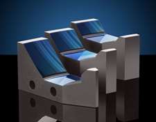
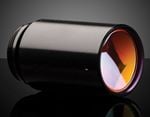
Reflective beam expanders utilize curved mirrors instead of transmissive lenses to expand a beam (圖 9). Reflective beam expanders are much less common than transmissive beam expanders, but have several advantages that make them the right choice for certain applications. Reflective beam expanders do not suffer from chromatic aberration, whereas the magnification and output beam collimation of transmissive beam expanders is wavelength dependent. While this is not relevant for many laser applications because lasers tend to lase at a single wavelength, it may be critical in broadband applications. The achromatic performance of reflective beam expanders is required for multi-laser systems, some tunable lasers, and ultrafast lasers. Ultrafast lasers inherently span a broader wavelength range than other lasers due to their extremely short pulse duration. Quantum cascade lasers also benefit from reflective beam expanders as transmissive options may not exist at their operating wavelengths.
圖 9: Unlike transmissive beam expanders, the curved mirrors of this Canopus Reflective Beam Expander expand the incident laser beam. The holes on the side of the beam expander are integrated mounting features

Beam Expander Selection Guide
View NowEdmund Optics Products
The TECHSPEC® Scorpii Nd:YAG Beam Expanders are available for applications where cost is the driving factor. Featuring 2-element Galilean designs with diffraction limited performance at YAG wavelengths, the Scorpii Nd:YAG Beam Expanders offer a variety of magnification ranges from 2X to 10X ideal for prototyping and OEM integration.
The TECHSPEC® Vega Laser Line Beam Expanders provide excellent value with λ/10 performance at design wavelength for apertures up to 4 mm. Featuring laser line V-coats for Nd:YAG harmonics down to 266 nm, these Galilean Designs use Fused Silica elements and provide divergence adjustability.
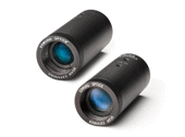
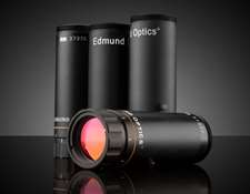
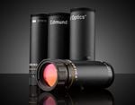
Examples of the application of the Galilean telescope design to laser beam expanders can be found in several Edmund Optics products, all of which can be used to collimate and focus laser beams. Our TECHSPEC® Arcturus HeNe Beam Expanders is a simple two-lens design, consisting of a negative lens and achromatic lens. Drawing of the internal optical elements is shown for reference.
Our TECHSPEC® Vega Broadband Beam Expanders feature broadband, divergence adjustable designs ideal for demanding tunable laser sources. They are optimized at a wide range of wavelengths and feature λ/10 transmitted wavefront error and no internally focusing ghost images, making them compatible with high power laser sources.

Our TECHSPEC® Draconis Broadband Beam Expanders improves upon the simple two-lens design with a proprietary multi-element lens design that enhances its ability to create a collimated or focused laser beam diameter at a long working distance.
The patent pending TECHSPEC® Canopus Reflective Beam Expanders are easily mounted due to a variety of integrated alignment features. They feature broadband performance with minimal wavefront distortion from the UV to Infrared from 250nm to 10μm. Their monolithic structure provides performance stability independent of changes in temperature.
Our TECHSPEC® Research-Grade Variable Beam Expanders can continuously adjust magnification and divergence while keeping a constant overall housing length. They are ideal for prototyping, R&D, and other applications requiring magnification adjustment.
References
- Greivenkamp, John E. Field Guide to Geometrical Optics. Vol. FG01. Bellingham, WA: SPIE—The International Society for Optical Engineers, 2004.
- Smith, Warren J. Modern Optical Engineering. 3rd ed. New York, NY: McGraw-Hill Education, 2000.
 精密雷射光學元件製造商

or view regional numbers
QUOTE TOOL
enter stock numbers to begin
Copyright 2023, Edmund Optics Inc., 14F., No.83, Sec. 4, Wenxin Road, Beitun District , Taichung City 406, Taiwan (R.O.C.)
California Consumer Privacy Act (CCPA): Do Not Sell My Information