需要我們的協助嗎?

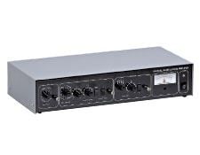
此類比雙相位鎖定放大器使用先進技術建立既具備多功能,又易於使用的高效能設備。鎖定放大器用於利用同步偵測程序來量測雜訊中所淹沒之訊號的幅度與相位,以恢復訊號。該放大器可充當窄帶帶通濾光片,移除大多數不需要的雜訊,同時允許要量測的訊號通過,從而實現上述功能。由參考訊號(必須向鎖定放大器提供參考訊號及未知訊號)設定要量測的訊號頻率,進而設定濾光片的通過頻寬範圍。The reference signal must be at the same frequency as the modulation of the signal to be measured. The front panel has three adjustment sections: Input, Output, and Reference. Power: 115V AC, 230V AC; 50-60Hz; 10VA max. Operating Temperature Range: 0-50°C. Amplifier operation can be split into 4 stages: an input gain stage, the reference circuit, a demodulator and a low pass filter.
The Input Signal Channel amplifies the input signal to a level suitable for the demodulator. High performance, low-noise, broadband amplifiers are used throughout. The input circuit can accept a differential or single-ended input via the front panel signal input BNC. Jumper options within the unit allow the outer BNC contact or screen to act as a high impedance differential input, as a low impedance (100 ohms) differential input or allow it to be connected to ground for single-ended operation. Through the careful design of the lock-in, up to ±10V of DC offset is allowed before saturation for gain settings from 1V to 300μV, ±1V of DC offset for gain settings from 100μV to 10μV and ±300mV of DC offset for the gain setting of 3μV.
The output of the signal input stage is processed using two very high bandwidth demodulators each operating 90° apart from each other to produce the X and Y signals. The X and Y outputs from the demodulator are passed through two first order, low pass filters and then amplified. The X and Y signals are combined to produce R the modulus signal, where R=(x2+y2)^½, before output via a front panel BNC.
The Reference Channel input circuitry uses a phase locked loop to lock on to a range of signals, such as TTL pulses or sinusoidal waveforms. A phase shifting circuit allows the reference signal to be moved with relation to the signal input. Signals at both the reference frequency and twice the reference frequency can be monitored.


or view regional numbers
QUOTE TOOL
enter stock numbers to begin
Copyright 2023, Edmund Optics Inc., 14F., No.83, Sec. 4, Wenxin Road, Beitun District , Taichung City 406, Taiwan (R.O.C.)
Privacy Policy | Cookie Policy | Terms & Conditions | Accessibility
California Consumer Privacy Act (CCPA): Do Not Sell My Information
The FUTURE Depends On Optics®