


所有關於非球面透鏡
入門: 非球面透鏡的優勢
球面像差校正
非球面透鏡最顯著的優勢,就是能夠進行球面像差校正。球面像差是使用球面表面聚焦或準直光線而產生。也就是說,所有的球面表面都會出現球差,無論是否存在任何測量誤差和製造誤差,因此需要不是球面或非球面的表面,對其進行校正。透過對圓錐常數和非球面係數進行調整,任何非球面透鏡均可得到優化,最大限度減小像差。例如圖1,展示了帶有顯著球面像差的球面透鏡,以及幾乎無球差的非球面透鏡。球透鏡產生的球差使入射光線在不同的位置聚焦,產生模糊的圖像;而在非球面透鏡中,所有不同的光線都會聚焦在同一點,因此相較而言產生的圖像不會模糊且質量更佳。
為了更好理解非球面透鏡和球面透鏡在聚焦性能方面的差異,請參考一個量化的範例,觀察兩個直徑25mm和焦距25mm的相等透鏡(f/1透鏡)。下表比較了軸上(0°物角)和軸外(0.5°和1.0°物角)的平行、單色光線(波長為587.6nm)所產生的光點或模糊大小。非球面透鏡的光斑尺寸比球面透鏡小幾個數量級。
圖 1:帶有球差的球透鏡,以及幾乎消除球差的非球面透鏡
| 物角 (°) | 0.0 | 0.5 | 1.0 |
| 球面光斑 (μm) | 710.01 | 710.96 | 713.84 |
| 非球面光斑 (μm) | 1.43 | 3.91 | 8.11 |
額外的性能優勢
儘管市面上還有許多不同的技術可校正球面像差,但這些其他技術在成像性能和靈活性方面,都遠遠不及非球面透鏡。另一種廣泛使用的技術是透過「縮小」透鏡來增加f/#。雖然這麼做可以提高成像品質,但也會減少系統中的光通量,因此這兩者之間有利有弊。
而使用非球面透鏡時,額外的像差校正可確保使用者在實現高光通量(低f/#,高數值孔徑)的系統設計同時,依然保持良好的圖像質量。稍微降低的圖像質量所提供的性能仍會高於球面系統所能提供的性能,因此更高的光通量設計所導致的圖像退化也可持續。以焦距81.5mm、f/2的三片式鏡頭(圖2)為例,第一種由三個球面表面組成,第二種為第一個表面是非球面表面(其餘為球面表面),這兩種設計均擁有完全相同的玻璃類型、有效焦距、視場、f/#,以及整體系統長度。下表對調製遞移函數(MTF) @ 20%對比度的軸上和軸外平行、多色的486.1nm、587.6nm、和656.3nm光線進行了定量比較。使用了非球面表面的三片式鏡頭,在所有視場角度均展現了更高的成像性能,其高切向解析度和高矢狀解析度,與只有球面表面的三片式鏡頭相比高出了三倍。
圖 2:多色光,通過三片式鏡頭
| 物角 (°) | 所有表面均為球面表面 | 第一表面為非球面表面 | ||
|---|---|---|---|---|
| 切向 (lp/mm) | 矢狀 (lp/mm) | 切向 (lp/mm) | 矢狀 (lp/mm) | |
| 0.0 | 13.3 | 13.3 | 61.9 | 61.9 |
| 7.0 | 14.9 | 13.1 | 31.1 | 40.9 |
| 10.0 | 17.3 | 14.8 | 36.3 | 41.5 |
系統優勢
非球面透鏡允許光學元件設計者使用比傳統球面元件更少的光學元件來校正像差,因為前者所提供的像差校正要多於後者使用多個表面所提供的像差校正。例如,一般使用十個或更多透鏡的變焦鏡頭,可以使用一兩個非球面透鏡替代五六個球面透鏡,並可實現相同或更高的光學效果、降低生產成本,同時也可縮小系統大小。
使用更多光學元件的光學系統可能會對光學和機械參數產生負面影響,因而帶來更昂貴的機構公差、額外的校準流程,以及更多的抗反射膜需求。最終以上所有結果均會降低系統的整體實用性,導致使用者將不得不持續增加支援組件。因此,在系統中加入非球面透鏡(雖然非球面透鏡價格相比f/#同等單片透鏡和雙合透鏡貴),實際上會降低整體系統設計成本。
剖析非球面透鏡
「非球面透鏡」的術語涵括任何不屬於球面的物件,然而此處使用該術語是指具體談論非球面透鏡的子集,即具有曲率半徑且半徑沿透鏡中心呈徑向改變的旋轉對稱光學元件。非球面透鏡能夠改善成像品質,減少所需的元件數量,同時降低光學設計的成本。從數位相機和CD播放機,到高端顯微鏡物鏡和螢光顯微鏡,非球面透鏡無論是在光學、成像或光子學行業的任一方面,其應用發展都非常迅速,這是因為相比傳統的球面光學元件而言,非球面透鏡擁有許多獨特又明顯的優勢。
非球面透鏡的傳統定義如公式1所示(由表面輪廓(sag)定義):
其中:
Z = 平行於光軸的表面的表面輪廓
s = 與光軸之間的徑向距離
C = 曲率,半徑的倒數
k = 圓錐常數
A4、A6、A8...= 第4、6、8… 次非球面係數
當非球面係數相等於零時,所得出的非球面表面就相等於一個圓錐。下表顯示,所產生的實際圓錐表面將取決於圓錐常數的量值大小以及正負符號。
| 圓錐常數 | 圓錐表面 | |
|---|---|---|
| k = 0 | 球面 | 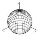 |
| k > -1 | 橢圓 | 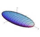 |
| k= -1 | 抛物面 | 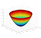 |
| k < -1 | 雙曲面 | 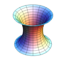 |
非球面透鏡獨具特色的幾何特徵就是其曲率半徑會隨著與光軸之間的距離而出現變化,相較之下,球面的半徑始終不變(圖3)。這種特殊形狀允許非球面透鏡提供相較於標準球面表面更出眾的光學性能。
圖 3:球面與非球面的表面輪廓比較
在過去幾年,另兩種使用正交項且逐漸普及的定義為Q-type非球面透鏡。這類Q型非球面透鏡,Qcon以及Qbfs使得設計師可以使用正交係數更好地控制非球面透鏡的優化過程,同時可降低製作非球面透鏡所需的條件。
製造過程?非球面透鏡類型
精密玻璃成型
精密玻璃成型是一種製造技術,將光學玻璃核心加熱至高溫使其表面具有足夠的可塑性,透過非球面模造成型(圖4),然後,逐步冷卻至室溫,光學玻璃核心仍將保持模造的形狀。創造模造有很高的初始啟動成本,因為必須使用高度耐用又能保持表面光滑的材料精確製造,要能夠顧及玻璃核心會發生的任何收縮,以製造出所需的非球面模造形狀。不過,當模造完成之後,其製造每個透鏡所需的邊際成本都會低於標準製造技術的邊際成本,因此,特別適用於需要進行大批量生產的場合。
圖 4:精密玻璃成型平臺
精密拋光
數年來,非球面透鏡在進行機器加工時需要逐一進行磨砂與拋光。雖然逐一製造加工非球面透鏡的流程並沒有很大改變,但製造技術提高卻提升了此製造技術所能實現的最高精確度。最顯著的是,經電腦控制的精密拋光(圖5)能夠自動調整工具駐留參數以便為需要較多拋光的高點進行拋光。如果需要較高的拋光質量,則可使用磁流拋光技術(magneto-rheological finishing, MRF)完善表面(圖6)。相較於標準拋光技術,MRF技術可精確控制去除位置同時擁有高去除率,因此能在較短的時間內實現高性能拋光。其他製造技術一般需要特別的模具,每款透鏡均有獨家模具,而拋光是使用標準工具,因此拋光成為原型製造以及少量生產應用的首要選擇。
圖 5:電腦控制拋光
圖 6:磁流拋光(MRF)
混合成型
混合成型是以消色差透鏡的標準球面表面為基材,透過含薄層光敏聚合物的非球面模造,將該球面表面壓鑄成型,最終製造出非球面表面。這項技術使用鑽石磨砂非球面模造和玻璃消色差透鏡(雖然也可以使用其他類型的單片透鏡和雙合透鏡),在非球面模造內注入光敏聚合物,再讓非球面模造將球面表面壓鑄成型。最後透過室溫壓縮和UV固化這兩個表面,製作出非球面消色差透鏡。該透鏡的光學屬性結合了所組成部件各自的光學屬性:消色差和球面像差校正。圖7為混合透鏡的製作過程。混合成型非常適用於高批量高精密的應用,除了滿足極高性能需求之外,還可以用批量生產削減初期開模高額成本。關於使用混合流程製作非球面消色差透鏡的更多資訊,請參閱為什麼使用消色差透鏡。

圖 7:混合成型技術
塑膠模造
除上述玻璃製造技術之外,市面上還有獨特的塑膠製造技術。塑膠模造是在非球面模造中注入熔融塑膠。相對於玻璃,塑膠的熱穩定性和抗壓性較差,因此需經過特別處理方可得到同等非球面透鏡。但塑膠有重量輕、易成型的優勢,可以與夾持件整合,獲得單一模組。雖然光學質量的塑膠選擇有限,但塑膠非球面透鏡的成本低、重量輕,因此有些應用更適合塑膠透鏡。
非球面透鏡各類型的不同優勢
所有應用所需的透鏡性能並不相同,因此選擇合適的非球面透鏡非常重要。需考慮的關鍵因素包括專案時間表、整體性能需求、預算限制以及預估數量。
透鏡現貨可立即供應,且訂單履約便利,因此許多應用可能已滿足於使用現貨非球面透鏡。但這些標準非球面透鏡往往可利用抗反射膜進行快速簡易修改,或縮減尺寸以滿足標準產品的需求。如果現貨產品供不應求,可考慮為原型製造、預製造或大量製造應用採用客製非球面透鏡製造。
| 類型 | 優勢 |
|---|---|
| 精密玻璃成型非球面透鏡 | 非常適用於大批量生產,因為可以迅速生產大量透鏡,工具維護成本底。 |
| 精密拋光非球面透鏡 | 非常適用於小批量生產,因為交貨時間短,只需少量特殊工具,設置簡單。 |
| 混合成型非球面透鏡 | 非常適用於多光譜應用,因為可以同時提供球差和消色像差校正。 |
| 塑膠模造非球面透鏡 | 非常適用於大批量生產,是低成本、輕重量的非球面透鏡替代品。 |
非球面製造規格
| 商業級 | 精密級 | 高精密級 | |
| 直徑 | 10 – 150mm | 10 – 150mm | 10 – 150mm |
| 直徑公差 | +0/-0.100mm | +0/-0.025 | +0/-0.010 |
| 非球面面形偏移 (P - V) | 3μm | 1μm | <0.06μm* |
| 頂點半徑 (非球面) | ±0.5% | ±0.1% | ±0.05% |
| 凹陷 | 25mm max | 25mm max | 25mm max |
| 典型面型坡度誤差 | 1μm/1mm 窗鏡 | 0.35μm/1mm 窗鏡 | 0.15μm/1mm 窗鏡 |
| 中心 (光束偏移) | 3 arcmin | 1 arcmin | 0.5 arcmin |
| 中心厚度公差 | ±0.100mm | ±0.050mm | ±0.010mm |
| 表面質量 | 80–50 | 40–20 | 10–5 |
| 非球面表面量測 | 輪廓測量(2D) | 輪廓測量(2D & 3D) | 干涉測量 |
* 在波長為 632.8nm 時僅有 1/10,受設計和/或量測技術限制
非球面透鏡選擇指南
| 非球面透鏡選擇指南 | |
| 精密拋光非球面鏡片 | |
|
經精密拋光的非球面透鏡適用於條件最為嚴苛的應用。其設計旨在達到繞射極限的光斑尺寸的同時提供高數值孔徑。
|
|
| 精密模造的非球面透鏡 | |
 精密模造的非球面透鏡非常適用於批量應用,包括雷射二極體校準、條碼掃描和光學資料儲存。
|
|
| 可校正色差的非球面透鏡 | |
|
提供多種特有非球面透鏡,旨在提供球差和色差校正。這些系列非常適合應用於波長範圍內需要近繞射極限聚焦性能的應用。
|
|
| 紅外非球面透鏡 | |
|
從適用於中波紅外量子級聯雷射的小型模造非球面到一系列鍍鍺和硒化鋅的非球面。提供適用於NIR到18μm的整個紅外光譜的解決方案。
|


or view regional numbers
QUOTE TOOL
enter stock numbers to begin
Copyright 2023, Edmund Optics Inc., 14F., No.83, Sec. 4, Wenxin Road, Beitun District , Taichung City 406, Taiwan (R.O.C.)
Privacy Policy | Cookie Policy | Terms & Conditions | Accessibility
California Consumer Privacy Act (CCPA): Do Not Sell My Information
The FUTURE Depends On Optics®