


擴束鏡測試
雷射擴束鏡用於在廣泛的雷射應用中提高準直輸入光束的直徑。在說明擴束鏡的品質特徵時,對其穿透波前差或離開擴束鏡的波前距理想形狀的偏差進行測試非常關鍵。分析穿透波前差可確定像差對擴束鏡性能的影響。
波前是光波具有恒定相位的表面。由於波前垂直於波的傳播方向,因此準直光具有平面波前,而聚焦或發散光具有彎曲波前(圖 1)。光學元件的像差會導致穿透或反射波前發生畸變,這稱為穿透或反射波前誤差。
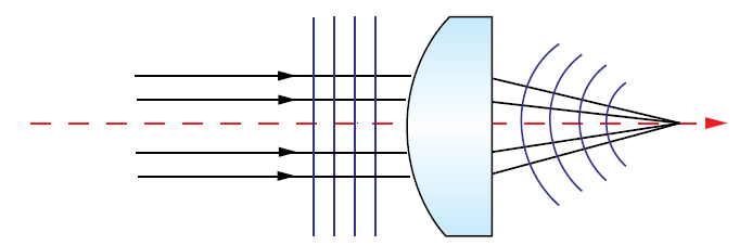
圖 1:進入透鏡的完美準直光具有平面波前,而在無像差的完美透鏡後的聚光具有以聚焦點為中心的球面波前
Shack-Hartmann 波前感測器 (SHWFS) 通常用於在擴束鏡測試中憑藉高動態範圍和準確性來測定穿透波前誤差。SHWFS 由相同微透鏡(即小透鏡)的陣列構成,每個微透鏡會將部分入射光聚焦到檢測器陣列的小區域上 (圖 2)。
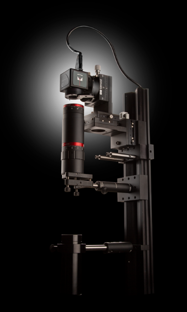
圖 2:Shack-Hartmann 波前感測器由於響應快、易於使用且成本相對較低,因此廣泛用於對擴束鏡的穿透波前誤差進行測試。
對於具有平面波前的完美準直入射光,將聚焦於聚焦點網格(以各微透鏡中心之間的距離分隔)中。若入射光包含波前誤差,將導致檢測器上的聚焦點位置發生變化(圖3)。該位移或聚焦點上強度的降低將用於確定陣列中各微透鏡上波前入射的局部傾斜。隨後,會使用各傾斜來近似模擬完整的入射波前。
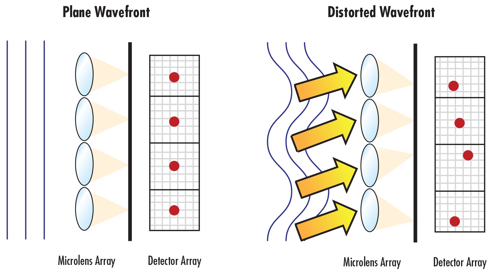
圖 3:進入 SHWFS 的入射光波中的波前誤差會導致感測器陣列上的聚焦點位置發生位移
一般而言,每個微透鏡的聚焦點應在相應的感測器部分涵蓋至少十個畫素,以便準確重建入射波前。聚焦點涵蓋的感測器區域增大時,SHWFS 的靈敏度也會升高。但是,這會付出動態範圍減小的代價,需要對兩者進行權衡。依照以往經驗,各微透鏡的聚焦點涵蓋範圍不應超過所關聯感測器部分的一半,以便在靈敏度和動態範圍之間取得合理平衡。1
透過增加陣列中的微透鏡數量,減少必須執行的波前斜率平均計算數量,可以使捕獲的資料點數量倍增。但增加微透鏡數量也會減少為各微透鏡分配的畫素數量。數量較少的較大微透鏡可能不足以對複雜的波前進行採樣,可能會導致對重建的波前進行人工平滑,但較大的微透鏡會更精確、更靈敏地測量緩慢變化的波前。2 在測試雷射擴束鏡時,必須考慮到所有這些權衡。
以波數量的形式指定雷射擴束鏡的穿透波前。例如,若針對 532nm 波長設計的擴束鏡具有 λ/10 的 P-V(峰谷值)穿透波前誤差,則與理想輸出波前相比允許畸變最大數量的計算方式為:
若擴束鏡的穿透波前誤差為 λ/4,則一般會將該擴束鏡視為達到「繞射極限」。
| 擴束鏡理論 | 擴束鏡選擇指南 | 旋轉與滑動擴束鏡對焦機制 |
| 進一步瞭解 | 進一步瞭解 | 進一步瞭解 |
參考文獻
- Forest, Craig R., Claude R. Canizares, Daniel R. Neal, Michael McGuirk, and Mark Lee Schattenburg. "Metrology of thin transparent optics using Shack-Hartmann wavefront sensing." Optical engineering 43, no. 3 (2004): 742-754.
- John E. Greivenkamp, Daniel G. Smith, Robert O. Gappinger, Gregory A. Williby, "Optical testing using Shack-Hartmann wavefront sensors," Proc. SPIE 4416, Optical Engineering for Sensing and Nanotechnology (ICOSN 2001), (8 May 2001); doi: 10.1117/12.427063


or view regional numbers
QUOTE TOOL
enter stock numbers to begin
Copyright 2023, Edmund Optics Inc., 14F., No.83, Sec. 4, Wenxin Road, Beitun District , Taichung City 406, Taiwan (R.O.C.)
Privacy Policy | Cookie Policy | Terms & Conditions | Accessibility
California Consumer Privacy Act (CCPA): Do Not Sell My Information
The FUTURE Depends On Optics®