


Introduction to Polarization
Understanding and manipulating the polarization of light is crucial for many optical applications. Optical design frequently focuses on the wavelength and intensity of light, while neglecting its polarization. Polarization, however, is an important property of light that affects even those optical systems that do not explicitly measure it. The polarization of light affects the focus of laser beams, influences the cut-off wavelengths of filters, and can be important to prevent unwanted back reflections. It is essential for many metrology applications such as stress analysis in glass or plastic, pharmaceutical ingredient analysis, and biological microscopy. Different polarizations of light can also be absorbed to different degrees by materials, an essential property for LCD screens, 3D movies, and glare-reducing sunglasses.
Understanding Polarization
Light is an electromagnetic wave, and the electric field of this wave oscillates perpendicularly to the direction of propagation. Light is called unpolarized if the direction of this electric field fluctuates randomly in time. Many common light sources such as sunlight, halogen lighting, LED spotlights, and incandescent bulbs produce unpolarized light. If the direction of the electric field of light is well defined, it is called polarized light. The most common source of polarized light is a laser.
Depending on how the electric field is oriented, we classify polarized light into three types of polarizations:
- Linear polarization: the electric field of light is confined to a single plane along the direction of propagation (Figure 1).
- Circular polarization: the electric field of the light consists of two linear components that are perpendicular to each other, equal in amplitude, but have a phase difference of π/2. The resulting electric field rotates in a circle around the direction of propagation and, depending on the rotation direction, is called left- or right-hand circularly polarized light (Figure 2).
- Elliptical polarization: the electric field of light describes an ellipse. This results from the combination of two linear components with different amplitudes and/or a phase difference that is not π/2. This is the most general description of polarized light, and circular and linear polarized light can be viewed as special cases of elliptically polarized light (Figure 3).
Figure 1: The electric field of linearly polarized light is confined to the y-z plane (left) and the x-z plane (right), along the direction of propagation.

Figure 2: The electric field of linearly polarized light (left) consists of two perpendicular, equal in amplitude, linear components that have no phase difference. The resultant electric field wave propagates along the y = x plane. The electric field of circularly polarized light (right) consists of two perpendicular, equal in amplitude, linear components that have a phase difference of π/2 or 90°. The resultant electric field wave propagates circularly.


Figure 3: The circular electric field (left) has two components which are of equal amplitude and have a π/2 or 90° phase difference. If the two components however, have differing amplitudes, or if there is a phase difference other than π/2, then then they will create elliptically polarized light (right).
The two orthogonal linear polarization states that are most important for reflection and transmission are referred to as p- and s-polarization. P-polarized (from the German parallel) light has an electric field polarized parallel to the plane of incidence, while s-polarized (from the German senkrecht) light is perpendicular to this plane.
Figure 4: P and S are linear polarizations defined by their relative orientation to the plane of incidence.
Manipulating Polarization
Polarizers
In order to select a specific polarization of light, polarizers are used. Polarizers can be broadly divided into reflective, dichroic, and birefringent polarizers. More detailed information on which type of polarizer is right for your application can be found in our Polarizer Selection Guide.
Reflective polarizers transmit the desired polarization while reflecting the rest. Wire grid polarizers are a common example of this, consisting of many thin wires arranged parallel to each other. The light that is polarized along these wires is reflected, while light that is polarized perpendicular to these wires is transmitted. Other reflective polarizers use Brewster’s angle. Brewster’s angle is a specific angle of incidence under which only s-polarized light is reflected. The reflected beam is s-polarized and the transmitted beam becomes partially p-polarized.
Dichroic polarizers absorb a specific polarization of light, transmitting the rest; modern nanoparticle polarizers are dichroic polarizers.
Birefringent polarizers rely on the dependence of the refractive index on the polarization of light. Different polarizations will refract at different angles and this can be used to select certain polarizations of light.
Unpolarized light can be considered a rapidly varying random combination of p- and s-polarized light. An ideal linear polarizer will only transmit one of the two linear polarizations, reducing the initial unpolarized intensity I0 by half,
For linearly polarized light with intensity I0, the intensity transmitted through an ideal polarizer, I, can be described by Malus’ law,
Where θ is the angle between the incident linear polarization and the polarization axis. We see that for parallel axes, 100% transmission is achieved, while for 90° axes, also known as crossed polarizers, there is 0% transmission. In real-world applications the transmission never reaches exactly 0%, therefore, polarizers are characterized by an extinction ratio, which can be used to determine the actual transmission through two crossed polarizers.
Waveplates
While polarizers select certain polarizations of light, discarding the other polarizations, ideal waveplates modify existing polarizations without attenuating, deviating, or displacing the beam. They do this by retarding (or delaying) one component of polarization with respect to its orthogonal component. To help you determine which waveplate is best for your application, read Understanding Waveplates. Correctly chosen waveplates can convert any polarization state into a new polarization state and are most often used to rotate linear polarization, to convert linearly polarized light to circularly polarized light, or vice versa.
Applications
Implementing polarization control can be useful in a variety of imaging applications. Polarizers are placed over a light source, lens, or both, to eliminate glare from light scattering, increase contrast, and eliminate hot spots from reflective objects. This either brings out more intense color or contrast or helps to better identify surface defects or other otherwise hidden structures.
Reducing Reflective Hot Spots & Glare
In Figure 5, a linear polarizer was placed in front of the lens in a machine vision system to remove obfuscating glare such that an electronic chip could be clearly seen. The left image (without polarizer) shows randomly polarized light scattering off of the many glass surfaces between the object and the camera sensor. Much of the chip is obscured by Fresnel reflection of the unpolarized light. The image on the right (with polarizer) shows the chip without glare obscuring any of the object details, allowing the chip to be viewed, analyzed, and measured without obstruction.
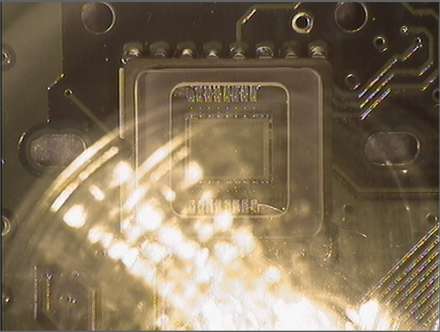
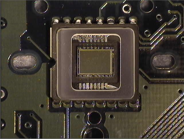
Figure 5: A polarizer is placed in front of the lens of a machine vision camera, reducing the stray light coming from a reflective surface between the lens and electronic chip.
The same phenomenon can be seen in the Figure 6. In the left image (without polarizer), unpolarized light from the sun is interacting with the windows of the Edmund Optics building and most of this light is reflecting off the windows. In the right image, a polarizing filter has been applied such that the reflected light, rich in one polarization type, is being blocked from the camera sensor and the photographer, using the other polarization type, can see into the building more easily.
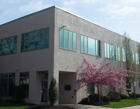
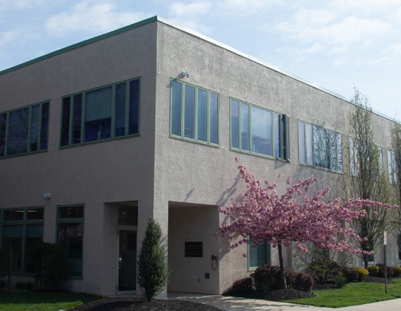
Figure 6: A polarizer is placed in front of the lens of a DSLR camera, reducing the glare coming from the partially reflective surface of the leaves on the vegetation.
Another characteristic way to see how polarizers reduce reflective glare is by viewing water surfaces. In Figure 7, the surface of the water appears reflective in the left image, obscuring what is below the surface. On the right, however, the rocky debris on the floor of the body of water is much more clearly visible.


Figure 7: A polarizer is placed in front of the lens of a DSLR camera reducing the glare coming from the partially reflective surface of the water.
Hot spots are highly reflective portions of a field within a more diffuse reflecting field. In Figure 8, a polarizer is placed in front of the lens of a camera as well as over the light source illuminating the scene to reduce hot spots.
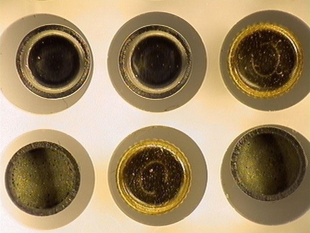
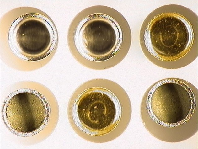
Figure 8: One linear polarizer is placed over the light source while another polarizer with a perpendicular orientation to the first one is placed over the lens of the camera to eliminate hot spots.
By cross-polarizing light with two linear polarizers that are oriented perpendicularly, hot spots can be reduced or eliminated altogether.
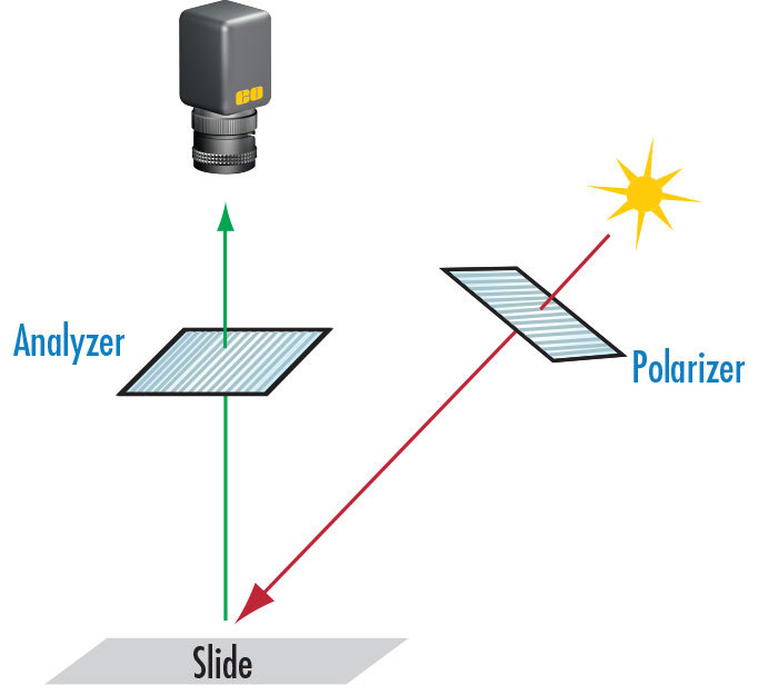
Figure 9: This imaging scheme is one way to eliminate or reduce scatter, glare, or hot spots. The light source is polarized by the polarizer and the reflected light that will be imaged is polarized once more, this time by the analyzer.
The angular difference between the axes of polarization of the two polarizers is directly related to the amount of overall light attenuation of the set of polarizers. By changing the angle offset, the optical density of the polarizer set can be varied, achieving a similar effect to using a neutral density filter. This ensures that the overall field is evenly illuminated.
Improving Contrast and Color Effects
Ring light guides are popular illumination sources due to their even, diffuse illumination. However, glare or reflection of the ring itself may occur. Polarizing the ring light output and the lens separately can reduce these effects, and bring out surface details as seen in Figure 9.
Figure 10: Polarizing the ring light output and the lens separately can greatly reduce glare effect to reveal important surface details.
Figure 11 shows a photo taken of Edmund Optics Headquarters and the variation in the color of the sky, grass, and foliage from using or not using a polarizer in front of a camera lens. Because electrons in air molecules scatter light in many directions, the appearance of the sky without a polarizer is a lighter shade of blue, as seen in the left image (without polarizer). Additionally, the surface of leaves of trees and on blades of grass are very slightly reflective. Using a polarizer filters out some of the light reflected from these surfaces, darkening the perceived color of these surfaces.


Figure 11: When photographing the sky, a polarizer in front of the lens can dramatically alter the color of the sky.
Stress Evaluation
In amorphous solids such as glass and plastic, stress from temperature and pressure profiles in the material imparts localized variations and gradients in the material properties, making the material birefringent and nonhomogeneous. This can be quantified in transparent objects using the photoelastic effect, as stress and its related birefringence can be measured with polarized light methodologies.
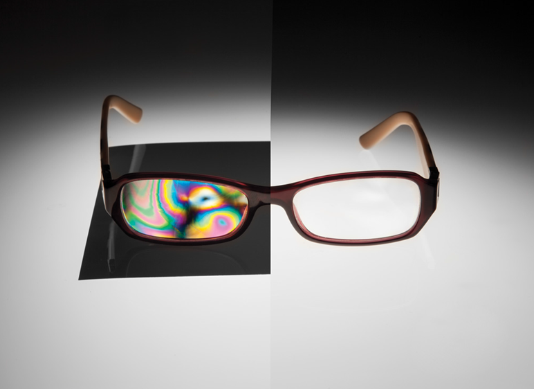
Figure 12: A pair of glasses appears clear without polarization; however, the use of polarizers makes visible the material stress variations and they appear as color variations.
Unstressed clear objects between crossed polarizers should yield a completely dark field, however, when internal material stress is present, the localized changes in refractive index rotate the angle of polarization, resulting in transmission variations.
Chemical Identification
Polarization control is also very important in the chemical, pharmaceutical, and food and beverage industries. Many important organic chemical compounds, such as active pharmaceutical ingredients or sugars, have multiple orientations. The study of molecules with multiple orientations is called stereochemistry.
Molecular compounds that have the same type and number of atoms, but different molecular arrangements are called stereoisomers. These stereoisomers are “optically active” and will rotate polarized light in different directions. The amount of rotation is determined by the nature and the concentration of the compound, allowing polarimetry to detect and quantify the concentration of these compounds. This is the premise for identifying which stereoisomer may be present in a sample, which is important because stereoisomers can have vastly different chemical effects. For example, the stereoisomer limonene is the chemical that gives oranges and lemons their characteristic scents.
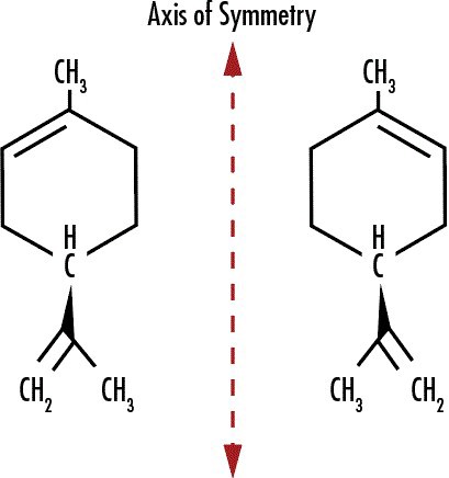
Figure 13: (+)-Limonene, or D-Limonene (left), is associated with the smell of oranges as oranges have a higher concentration of this stereoisomer than the other. (+)-Limonene rotates the orientation of incident light. (-)-Limonene, or L-Limonene (right), is associated with lemons because it is highly concentrated in lemons, and it rotates incident light in the opposite direction as (+)-Limonene.
Polarization Microscopy
Many different types of microscopy techniques such as differential interference contrast (DIC) microscopy utilize polarizers to achieve a variety of effects.
In a simple polarization microscope system, a linear polarizer is placed in front of a microscope light source, below the specimen stage, to polarize the light entering the system. Another linear polarizer placed above the specimen stage is referred to as an “analyzer,” as this polarizer is rotated to achieve the desired effect when analyzing the sample and while the first polarizer is kept stationary. The analyzer is then rotated such that the polarization planes of the analyzer and polarizer are 90° apart. When this has been achieved, the microscope has a minimum transmission (crossed polarizers); the amount of light transmission will be proportional to the extinction ratio of the polarizer and analyzer.
Once the analyzer has been aligned perpendicularly to the polarizer, an anisotropic, or birefringent, the specimen is placed on the specimen stage. The specimen rotates the polarized light a designated amount, proportional to the specimen thickness (and thus the optical path distance) and the specimen birefringence, before its light reaches the analyzer.
The analyzer only transmits light that has experienced a specimen-induced phase shift and continues to block all the unaffected light from the source which was originally polarized by the polarizer. If the birefringence of the specimen is known, it can then be used to determine the specimen thickness. If the specimen thickness is known, it can be used to deduce the birefringence of the specimen. A convenient chart used for this purpose is known as the Michel-Levy interference color chart in Figure 14.


or view regional numbers
QUOTE TOOL
enter stock numbers to begin
Copyright 2023, Edmund Optics Inc., 14F., No.83, Sec. 4, Wenxin Road, Beitun District , Taichung City 406, Taiwan (R.O.C.)
Privacy Policy | Cookie Policy | Terms & Conditions | Accessibility
California Consumer Privacy Act (CCPA): Do Not Sell My Information
The FUTURE Depends On Optics®