A Closer Look at Kinematic Movement
Edmund Optics Inc.

A Closer Look at Kinematic Movement

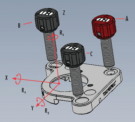
Mechanical systems can be classified according to the number of degrees of freedom (DOF) present. A three-dimensional rigid body has exactly 6 independent degrees of freedom: the translational (X, Y, Z) and the rotational (Rx, Ry, Rz). A mount is considered kinematic if all degrees of freedom are fully constrained. Figure 1 illustrates a kinematic mount.

TECHSPEC® Kinematic Mount Design Fully Constrains all 6 Degrees of Freedom
Figure 1: TECHSPEC® Kinematic Mount Design Fully Constrains all 6 Degrees of Freedom

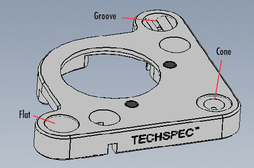
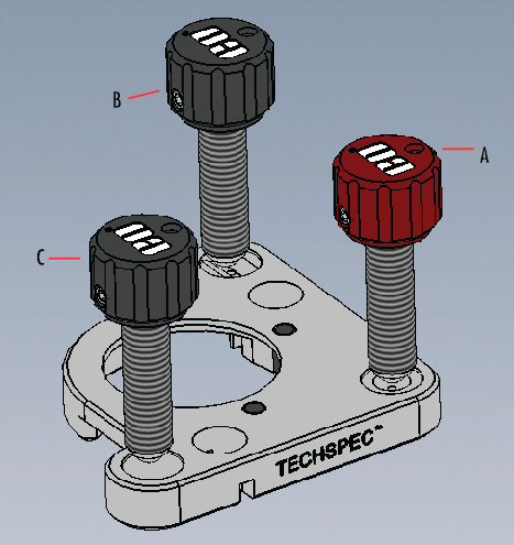
Edmund Optics®’ TECHSPEC® Kinematic Optical Mounts use the classic cone, groove, and flat constraint system. Figures 2 and 3 illustrate our 1" Dia. Kinematic Optic Mount. To visualize how the Kinematic Optic Mount functions, consider an optic being aligned in the coordinate system of the three adjustment screws.

Groove, Cone, and Flat Constraint System
Figure 2: Groove, Cone, and Flat Constraint System
Three Screw 1 Inch Diameter Kinematic Optic Mount
Figure 3: Three Screw 1" Diameter Kinematic Optic Mount

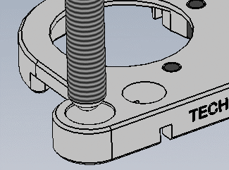
Placing the ball-tip of adjustment screw A into the cone constrains all translational degrees of freedom (X, Y, Z). When the groove is oriented along the x-axis, as shown in Figure 1, placing the ball-tip of adjustment screw B into the groove constrains two of the remaining three rotational degrees of freedom, (Ry, Rz). The final degree of freedom (Rx) is constrained by placing the ball-tip of adjustment screw C against the flat face (Figure 4).

Ball Tip Screw Against Flat Face Constrains the Rx Degree of Freedom
Figure 4: Ball Tip Screw Against Flat Face Constrains the Rx Degree of Freedom

Edmund Optics® offers Kinematic Mounts with either two or three adjustment screws. Two adjustment screws, at the groove and the flat, can be used to adjust the rotational degrees of freedom. In contrast to our example above, the axes of rotation are behind the optic when adjustment is made so a slight translation of the optic in the Z-axis also occurs.

A third screw can be placed over the cone to compensate for the unwanted translation. This three screw configuration enables the optic to be rotated as needed using the first two adjustment screws then returned to its original position along the Z-axis using the third.

這項內容對您是否實用?

相關產品


Sales & Expert Advice
 
or view regional numbers
Easy-to-Use
QUOTE TOOL
enter stock numbers to begin