


傳感器相對照明、衰减以及暗角
成像資源指南第3.2部份
要解決與相對照度(RI),亮度衰減問題,和漸暈現象(遮擋穿過成像鏡頭邊緣光線),必須考慮傳感器版面大小。有關傳感器詳情請參見 傳感器。
鏡頭和傳感器相匹配
經常出現的一個問題是,成像鏡頭能否支援到某些特定的傳感器尺寸。如果傳感器對鏡頭設計而言過大,則所產生的圖像看起來可能朝向邊緣區域逐漸消失或變暗;這一效果是由邊角失光造成的。隨著系統的解析度要求提高,需要做到兩點之一:像素需要變小,傳感器需要變大。如有關繞射極限和MTF的部份 解析度與對比度限制: 艾里斑 和 調制轉換函數(MTF)和MTF曲線中所詳述,持續縮小像素大小會產生伴隨光學鏡頭解析真正細節能力的重大問題。這個問題以及與目前傳感器技術有關的信噪比和敏感度問題會造成傳感器不得不增大尺寸,但如果沒有使用適當的鏡頭,尺寸增大又會導致與漸暈和衰减相關的問題。
相對照度

圖 1: 一組RI曲線在X軸方向顯示相關圖像傳感器版面數值。
圖 1 顯示了一條典型的RI曲線,其中圖像高度與相對亮度。 各個曲線代表不同 f/#下的RI性能。 注意,RI 不是絕對亮度。 較高的f/#值仍會導致整體亮度降低, (了解有關 f/# 的更多資料請參見 f/# (鏡頭光圈 / 光圈設定))。x 軸代表傳感器中心到傳感器周邊的距離。 y軸表示照明強度相對於整個視場任何位置中最高為 100% 的照度(通常是視場中心)RI。 若要找出鏡頭在不同傳感器上的 RI 性能,可利用傳感器對角線長的垂直方向標線位置尋找。 圖 2 是光圈 f/1.4 下 圖 1 中 RI 圖像相對照度模擬。

圖 2: 此圖顯示的藍色f/1.4曲線在2/3”圖像傳感器中會如何顯示。
圖 1中的曲線顯示,在最低光圈設定(f/1.4 – 藍線)下,此鏡頭的相對照明為 2/3”傳感器邊角處之圖像中心的照明度的 57%。相同條件下,鏡頭相對照明為 1/2”傳感器邊角處的 72%。隨著傳感器變小,相對照明會提高。另請注意,相對照明會隨f/#增加而提高;這種情況會持續到鏡頭中不再出現邊角失光,這時,所有較高的f/#設定都具有相同的照明分佈。增大f/#通常不會大幅提高圖像圈大小,因為即使縮小f/#,針對特定傳感器大小設計的鏡頭也無法在較大傳感器上獲得出色的效能。
縮小光圈後,仍然會發生衰减,因為衰減與光線角度有關,而與穿過鏡頭的光線數無關。許多鏡頭都會具有視場中間最高的照明分佈,並在靠近邊緣時持平或降低到某個更低的百分比。在極少數情況下,圖像圈內的相對照明會略微提高,但這與光瞳壓縮相關,本文中對此不做介紹。
鏡頭的漸暈現象 - 進階
漸暈是由於進入傳感器的光線被某個鏡片邊緣或機械結構阻擋而未穿過整個鏡頭系統產生的現象。這種光線裁剪可能是特意或無意的,在某種情況下不可避免。。邊角失光最常見於低f/#、短焦距鏡頭,或需要在較低成本下實現提高鏡頭分辨率。
圖 3 展示了相同16mm鏡頭於不同f/#(f/1.8和f/4)下可能出現的裁剪。請注意 圖 3a, 中用紅圈標出的光線裁剪;這些光線無法穿過鏡頭中的所有光學鏡片。另一方面,圖 3b, 展示了沒有漸暈的範例。 圖 3a 中的漸暈可能具有多種原因,包括光學鏡片的直徑限制,或需要消除光線以阻擋雜散光。鏡頭設計中有時會有意包含漸暈以提高整隻鏡頭性能或降低成本。


圖 3: f/1.8 (a)和f/4 (b)下的16mm鏡頭設計。f/1.8光圈下用圓圈表示邊角失光出現在光線被鏡片邊緣遮擋。
選擇漸暈來提高性能 - 進階
漸暈通常用於提高鏡頭設計在整個成像範圍內的最大分辨率。由於將圖像周邊的光線入射到傳感器上所需位置更困難,因此在圖像邊緣要再現解析度較高的物件一般比在中央位置更難。最終位於錯誤像素上的光線會降低此位置的圖像品質;控制的方法是消除這些來自系統的光線。如果把這些不想要的光線不進入傳感器,則不會降低圖像品質。不過,消除這些偏差的光線會降低相對照明性能。
Vignetting at the Pixel Level: Large vs. Small Pixels
圖 4 illustrates light rays incident on a pixel in the corner and center of a sensor at f/1.4 (a and b) and f/2.8 (c and d). In 圖 4a, some light spills onto the adjacent pixel creating slight image and contrast degradation. Increasing the f/# (圖 4c) essentially creates vignetting which clips those extraneous rays and improves image contrast. 圖 5 illustrates this same vignetting effect with smaller pixels. However, with the larger pixels in 圖 4, the change in f/# has much less of an effect on the overall image quality, because it occurs over a smaller number of pixels.

圖 4: Light rays incident pixels in the corner of a sensor at f/1.4 (a and b), and f/2.8 (c and d). Increasing the f/# creates vignetting which clips the extraneous rays spilling onto the adjacent pixel in (a) and improves contrast.
In 圖 5, the pixels have been reduced to half the size, yielding a 4X resolution increase. In this example, vignetting by increasing f/# greatly, improves performance across the entire sensor, as opposed to the first example which only slightly improved the imaging performance in the corner of the image.

圖 5: Light rays incident on pixels in the center of a sensor at f/1.4 (a and b), and f/2.8 (c and d). For large pixels, increasing the f/# has a less significant effect on image quality as all rays were nearly contained in the desired pixel. For small pixels, increasing the f/# creates vignetting which prevents the extraneous rays from spilling onto nearby pixels.
圖 4 and 圖 5 exhibit nominal design capabilities and do not account for reduced performance that results from manufacturing tolerances. With tolerances included, the need for vignetting can be even more pronounced, especially in cases where cost is a driving factor.
Vignetting can also be purposefully designed into lenses in scenarios in which the effects from manufacturing tolerances adversely affect the control of rays, causing image degradation. The looser the tolerances on the lens, the more adverse these degrading effects can become, and tightening the tolerances is often not practical due to the increase in manufacturing cost. Often, a balance must be struck between reducing manufacturing cost and maintaining image quality. In cases where cost is a primary factor, vignetting must be utilized in an attempt maintain resolution across the field of view. Doing such will have an adverse effect on the illumination profile. Designing vignetting into a lens can be accomplished in a couple different ways: by purposefully designing the clear apertures of the individual lens elements such that they vignette severely off-axis rays, or by introducing mechanical apertures to block aberrated rays, as shown in 圖 8a.
Vignetting in Different Lens Designs - ADVANCED
圖 6 features a standard 12mm Lens design layout, along with both its relative illumination and MTF curves. Note the size difference of the ray bundles in 6a at the center (blue lines) and corner (green lines); the size difference demonstrates a large amount of selective vignetting. The vignetting leads to lower illumination at the edges of the image than in the center (6b). This is done to minimize the costs associated with materials and manufacturing tolerances, while maintaining reasonable performance at a lower price.


圖 6: A standard 12mm lens ray path (a), relative illumination curve (b), and MTF curve (c).
The lens in 圖 7, an ultra-high resolution 12mm lens design, has a much more evenly sized ray bundles across the field (7a) due to a low level of vignetting. This translates to much more even relative illumination across the entire sensor (7b). The lens in this example is designed using more costly materials at tighter tolerances, which allows it to maintain high levels of performance across the image, without the need to introduce vignetting to improve its performance. The trade off in using such a lens is that the ultra-high-resolution lens is more expensive than the standard design.


圖 7: An ultra-high-resolution 12mm lens ray path (a), relative illumination curve (b), and MTF curve (c).
亮度衰減 - 進階
亮度衰減是相對於不同視場位置RI下降,不是由漸暈引起的,是由輻射定律限制 圖 8有一個公式,敘述成像圈內沒有邊角失光的鏡頭的最大亮度受像空間內主光線角度的余弦的四次方限制。這被稱為 cos4θ roll-off (most often referred to as “cosine to the fourth” roll-off).
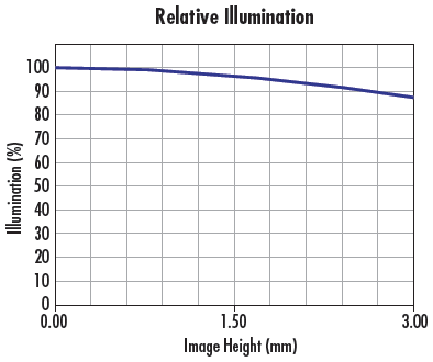
圖 8: 衰减是與視場相關的相對照明降低,這並非由邊角失光、而是由輻射定律造成。
圖 9 顯示了圖像中心和邊角處的主要光線(以紅色突出顯示)。許多應用中衰减都不是問題;但如果主光線角度變得非常陡峭,亮度衰減現象就會產生。在使用大型傳感器的應用、線掃描應用以及廣角視場(短焦距)

圖 9: 成像鏡頭結構圖,標示成像中心區(藍線)和周邊區域(綠線)的光束的主光線。這些光線定義了用於確定衰减近似值的角度。
表 1 顯示了衰减如何隨角度增加。請注意,對於 15°的角,相對照明從中心到邊角會降低約 13%,但將角度翻倍後,衰减程度會提高而相對照明降低約 44%。 在工作距離較短、視場較大的應用中,必須考慮衰減現象。這可能會在像空間中產生較大的主光線角度,與感測器大小無關。
| Chief Ray Angle | Maximum Relative Illumination Level Center to Corner |
|---|---|
| 5° | 98.5% |
| 10° | 94.0% |
| 15° | 87.1% |
| 30° | 56.3% |
| 45° | 25.0% |
| 60° | 6.3% |
表 1: 假設中心處的相對照明為100%,主光線角度與成像邊角處相對照明的關係。
修正衰减的方式之一是將鏡頭設計為像空間遠心。透過這種方式,主光線角度的差異是0°,這能產生均勻的照明。另一種減少衰减的方式是在受檢測物件上提供不對稱的照明。透過將其他燈光安裝在更靠近受檢測物件邊緣的位置,或在鏡頭上加入變跡中性密度濾光片,可以減少衰减。
周邊亮度衰減和微型透鏡 - 進階
許多傳感器都採用微型透鏡設計來有效像素區域內的收光量。與所有其他鏡頭一樣,微型透鏡也具有工作效率最高的收光角度。隨著入射角增大,使其成為有效像素區域的光線量將會減少。大多數鏡頭設計都嘗試將像空間主光線角度保持在5至7°以下,以降低這些影響。圖 10a 顯示了像素上方的微型透鏡。


圖 10: 主光線的入射角影響周邊成像區域相對照度。
圖 10b 和 圖 10c 分別顯示了光線在正入射和斜入射到微型透鏡時的聚焦情況。正入射會顯示傳感器上的中心像素。在此位置,所有光線都聚焦在有效像素區域上。在斜角處,並非所有光線均使其成為有效像素區域。這會造成vig相對照明進一步降低,低於鏡頭相對照明曲線上的設計值。


or view regional numbers
QUOTE TOOL
enter stock numbers to begin
Copyright 2023, Edmund Optics Inc., 14F., No.83, Sec. 4, Wenxin Road, Beitun District , Taichung City 406, Taiwan (R.O.C.)
Privacy Policy | Cookie Policy | Terms & Conditions | Accessibility
California Consumer Privacy Act (CCPA): Do Not Sell My Information