


抗反射 (AR) 鍍膜
這是 《雷射光學元件資源指南》的 第 11.3 節 。
愛特蒙特光學為所有 TECHSPEC® 穿透光學元件提供多種抗反射(AR)鍍膜選項,透過提高穿透率、增強對比度並消除重影,可顯著提升光學效能。大多數AR鍍膜還具有出色的耐久性,能同時抵禦物理損傷和環境侵蝕。基於這些優勢,絕大多數穿透光學元件均會配置某種形式的抗反射鍍膜。在為特定應用選擇AR鍍膜時,必須先充分瞭解系統的完整光譜範圍。雖然AR鍍膜能大幅提升光學系統性能,但在設計波長範圍之外的波段使用鍍膜反而可能降低系統性能。
為何選擇抗反射鍍膜?
由於菲涅耳反射效應,當光線從未鍍膜的玻璃基材穿過時,每個介面會反射約4%的入射光。這將導致系統總穿透率僅剩92%,在許多應用中會造成嚴重影響( 圖 1)。過量反射光不僅會降低通光效率,在雷射應用中還可能引發雷射誘導損傷。抗反射 (AR) 鍍膜應用於光學表面,可提高系統的光輸送量,並減少因後向反射穿過系統產生鬼影造成的危害。後向反射還會使雜散光進入雷射腔,導致雷射系統失穩。對於含有多組穿透光學元件的系統,AR鍍膜尤為重要。多數弱光系統都會採用 抗反射鍍膜光學元件 ,以實現光線的高效利用。
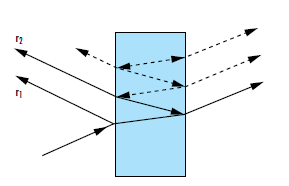
圖1:菲涅耳反射發生在所有介質介面。每當反射光線到達新的介面時,其部分能量會再次經歷菲涅耳反射1
抗反射(AR)鍍膜經過精密設計,使薄膜上下邊界反射光束產生180°的相對相位差。當兩束反射光發生相消干涉時,會在離開表面前即相互抵消(圖 2)。光學鍍膜厚度必須為$\tfrac{\lambda}{4}$的奇數倍,其中$ \small{\lambda} $ 為設計波長或最佳化峰值性能的波長,以實現反射光束之間 $\tfrac{\lambda}{2}$ 的所需光程差。滿足此條件時,將導致光束相消干涉。<35>折射率</35>實現反射光束完全相消干涉所需的薄膜折射率$ \small{\left( n_f \right)} $可透過入射介質折射率 $ \small{\left( n_0 \right)} $ 和基材折射率 $ \small{\left( n_s \right)} $計算得出。
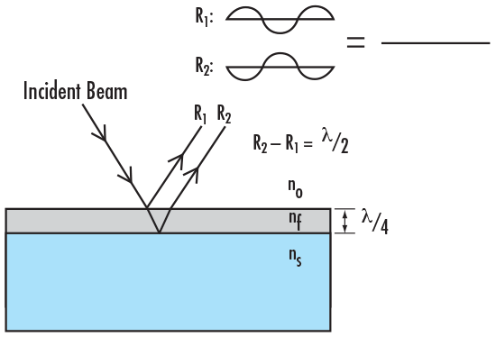
圖2:每一層鍍膜的折射率和厚度均經過精確控制,以實現各反射光束之間的相消干涉
抗反射V型鍍膜是一種特殊的AR鍍膜,設計用於在指定設計波長(DWL)為中心的極窄波段內提高穿透率。這種鍍膜被稱為「V型鍍膜」,因為其穿透率隨波長變化的曲線呈「V」形,在DWL處達到最低點。使用單頻、窄線寬雷射或窄半高寬(FWHM)光源時,V型鍍膜是實現最大穿透率的理想選擇。1 V型鍍膜在DWL處的反射率通常低於0.25%。但該鍍膜的反射曲線在局部呈現近似抛物線形狀,在DWL以外的波長處反射率會顯著升高(<52>圖3</52>)。
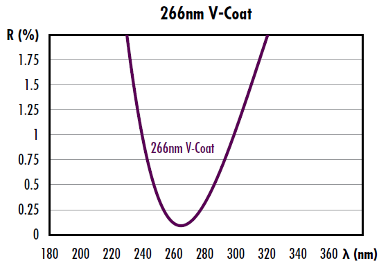
圖3:266nm雷射V型鍍膜範例(專為實現266nm波長最大穿透率而設計)
表 1 展示了EO公司標準雷射V型鍍膜的反射率及有保證的雷射誘導損傷閾值(LIDT)性能參數。
| 標準雷射V型鍍膜 | ||
|---|---|---|
| DWL (nm) | 鍍膜規格 | 損傷閾值,脈衝$\left(\tfrac{\text{J}{\text{cm}^2}\right)$ |
| 266 | R <0.25%@ DWL | 3 @ 266nm, 20ns, 20Hz |
| 343 | R <0.25%@ DWL | 7.5 @ 343nm, 20ns, 20Hz |
| 355 | R <0.25%@ DWL | 7.5 @ 355nm, 20ns, 20Hz |
| 515 | R <0.25%@ DWL | 10 @ 515nm, 20ns, 20Hz |
| 532 | R <0.25%@ DWL | 10 @ 532nm, 20ns, 20Hz |
| 980 | R <0.25%@ DWL | 10 @ 980nm, 20ns, 20Hz |
| 1030 | R <0.25%@ DWL | 15 @ 1030nm, 20ns, 20Hz |
| 1064 | R <0.25%@ DWL | 15 @ 1064nm, 20ns, 20Hz |
表1:反射率規格及雷射損傷閾值(LIDT)保證——適用於EO標準雷射V型鍍膜,可客製波長
由於當光源波長偏離設計波長(DWL)時反射率會急劇上升,V型鍍膜光學元件必須嚴格在鍍膜設計波長或近似波長的條件下使用。V型鍍膜的特性在於其穿透曲線呈半週期性:在DWL的諧波波長處(例如$ \tfrac{\lambda_0}{2} $ 或 $ \tfrac{\lambda_0}{4} $)會出現反射率局部極小值,但這些位置的反射率最佳化程度不如設計波長。V型鍍膜通常僅由兩層鍍膜構成。簡易V型鍍膜可能僅包含a $ \tfrac{\lambda}{4} $,度的單層膜,但若需調整頻寬或缺乏合適折射率的鍍膜材料時則需增加層數。多層鍍膜可補償不同入射角的影響,但結構更複雜且易導致頻寬增大。若V型鍍膜層厚誤差會導致反射率上升及設計波長偏移。Edmund Optics的V型鍍膜實際反射率通常遠低於0.25%,但所有標準V型鍍膜在設計波長處的反射率規格均為<0.25%。該容差設計可吸收鍍膜工藝導致的設計波長微小偏移。
寬頻抗反射膜(BBAR)專為更寬波段的穿透最佳化設計。適用於廣譜光源及多諧波生成雷射。BBAR鍍膜的反射率通常略高於V型鍍膜,但其寬廣的穿透波段具有更強通用性。除了應用於透鏡和窗鏡等穿透光學元件外,抗反射膜(AR)還被用於雷射晶體與非線性晶體,以最大限度地減少空氣與晶體接觸面產生的菲涅耳反射。1
寬頻抗反射膜(BBAR)鍍膜規格選項
Edmund Optics提供所有帶可選單層介電抗反射(AR)鍍膜的TECHSPEC®透鏡,以減少表面反射。此外,客製單層、多層、V和2V鍍膜可用於現貨及大批量客製訂單。相關資訊請查看客製光學透鏡塗層。

Figure 4: 波長選擇圖
$\tfrac{\lambda}{4}$ MGF2:最簡單的AR鍍膜是$\tfrac{\lambda}{4}$ MGF2,以550nm為中心(在550nm下折射指數為1.38)。MGF2 鍍膜是寬頻應用的理想之選,但其效果取決於所涉及的玻璃類型。
VIS 0° and VIS 45°: VIS 0°(0°入射角)和VIS 45°(45°入射角)提供425–675 nm的最佳穿透率,平均反射率分別降低到0.4%和0.75%。對於可見應用,VIS 0°AR鍍膜優於MGF2。
VIS-NIR可見光/近紅外寬頻抗反射膜經過特殊最佳化處理,可在近紅外波段實現最大穿透率(>99%)。
Telecom-NIR:電信/近紅外鍍膜是專為1200-1600nm通信波段設計的寬頻抗反射膜。
UV-AR和UV-Vis:紫外鍍膜應用於紫外熔融石英透鏡和紫外熔融石英窗鏡,以增強在紫外波段的性能表現。
NIR I和NIR II:近紅外I與近紅外II寬頻抗反射膜在常見光纖、雷射二極體模組和LED照明使用的近紅外波段具有卓越性能。
SWIR: 短波紅外寬頻AR鍍膜適用於900 - 1700nm的應用。
圖5、圖6和表2顯示了EO的標準Bbar鍍膜規格。
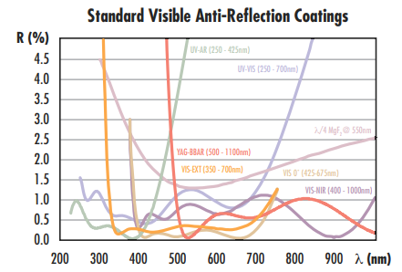
圖 5:EO標準可見光波段抗反射膜

圖6EO標準近紅外(NIR)波段抗反射膜涵蓋400-1600nm範圍,但可客製設計超過2µm的特殊鍍膜
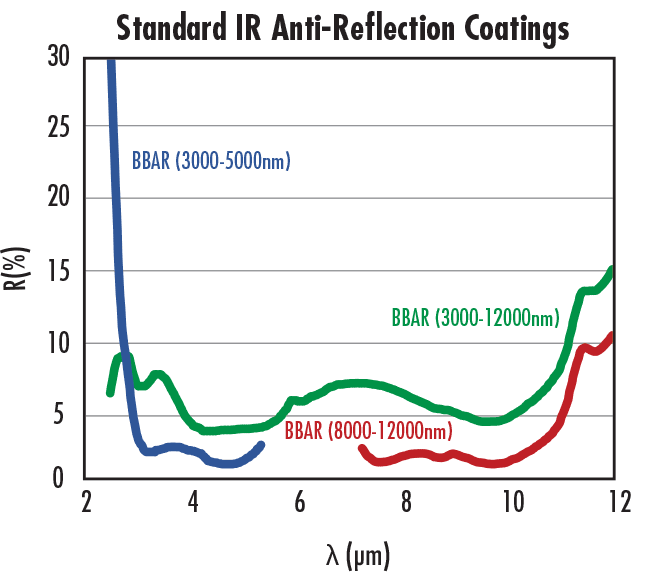
圖7:EO標準紅外(IR)波段抗反射膜
| 標準寬頻防反射鍍膜 | ||
|---|---|---|
| 鍍膜描述 | 規格 | 鍍膜曲線 |
| λ/4 MGF2 @ 550nm | Ravg ≤ 1.75% @ 400 - 700nm | 下載曲線 |
| UV-AR [250-425nm] | Rabs ≤ 1.0% @ 250 - 425nm< | 下載曲線 |
| Ravg ≤ 0.75% @ 250 - 425nm | ||
| Ravg ≤ 0.5% @ 370 - 420nm | ||
| 雷射紫外-可見光[250-532nm] | Rabs≤1.0% @ 250 - 532nm | 下載曲線 |
| 紫外-可見光[250-700nm] | Ravg≤0.75% @ 350 - 450nm | 下載曲線 |
| Ravg≤0.5% @ 250 - 700nm | ||
| VIS-EXT [350-700nm] | Ravg ≤ 0.5% @ 350 - 700nm | 下載曲線 |
| VIS-EXT+[350-700nm] | RABS <1.5%@ 350 - 700Nm @±30°AOI | 下載曲線 |
| Ravg <0.5% @ 350 - 700nm @ ±30° AOI | ||
| VIS-NIR [400-1000nm] | RABS≤0.25%@ 880nm | 下載曲線 |
| Ravg ≤ 1.25% @ 400 - 870nm | ||
| Ravg ≤ 1.25% @ 890 - 1000nm | ||
| 雷射可見光近紅外[500-1090nm] | Ravg ≤ 1.0% @ 500 - 1090nm | 下載曲線 |
| 視覺化0°[425-675nm] | Ravg ≤ 0.4% @ 425 - 675nm | 下載曲線 |
| YAG-Bbar [500-1100nm] | RABS≤0.25%@ 532nm | 下載曲線 |
| RABS≤0.25%@ 1064nm | ||
| Ravg≤1.0%@ 1100nm | ||
| 近红外I [600-1050nm] | Ravg ≤ 0.5% @ 600 - 1050nm | 下載曲線 |
| 近红外+ [600-1050nm] | RABS <1.5%@ 600 - 1050nm @±30°AOI | 下載曲線 |
| Ravg <0.5% @ 600 - 1050nm @ ±30° AOI/td> | ||
| 近红外II [750-1550nm] | Rabs ≤ 1.5% @ 750 - 800nm | 下載曲線 |
| Rabs ≤ 1.0% @ 800 - 1550nm | ||
| Ravg ≤ 0.7% @ 750 - 1550nm | ||
| SWIR [900-1700nm] | Ravg ≤ 1.0% @ 900 - 1700nm | 下載曲線 |
| Rabs ≤ 1.5% @ 900 - 1700nm | ||
| SWIR+[900-1700nm] | RABS <1%@ 900 - 1700nm @±30°AOI | 下載曲線 |
| Ravg <0.5% @ 900 - 1700nm @ ±30° AOI | ||
| 雷射近红外[1030-1550nm] | Ravg ≤ 0.7% @ 1030 - 1550nm | 下載曲線 |
| 2μm Bbar [1900-2100nm] | Ravg ≤ 0.5% @ 1900 - 2100nm | 下載曲線 |
| Rabs ≤ 0.25% @ 1900 - 2100nm | ||
表2:EO標準Bbar鍍膜的反射率規格
以下TECHSPEC®Optics提供抗反射鍍膜


參考文獻
- Paschotta, Rüdiger. Encyclopedia of Laser Physics and Technology, RP Photonics, October 2017, www.rp-photonics.com/encyclopedia.html
更多資源
- 光學鍍膜簡述
- 金屬鏡面鍍膜應用說明
- 高反射性鍍膜應用說明
- Laser Optics Lab: 鍍膜影片
- 明確瞭解雷射元件雷射損傷閾值(LIDT)的應用說明
- 修改Stock Optics Tip #4:如何在庫存透鏡上添加鍍膜
- 硬質鍍膜的優點應用說明
- [網路研討會] 雷射應用高反射鏡技術
- 雷射光學實驗室實景


or view regional numbers
QUOTE TOOL
enter stock numbers to begin
Copyright 2023, Edmund Optics Inc., 14F., No.83, Sec. 4, Wenxin Road, Beitun District , Taichung City 406, Taiwan (R.O.C.)
Privacy Policy | Cookie Policy | Terms & Conditions | Accessibility
California Consumer Privacy Act (CCPA): Do Not Sell My Information
The FUTURE Depends On Optics®